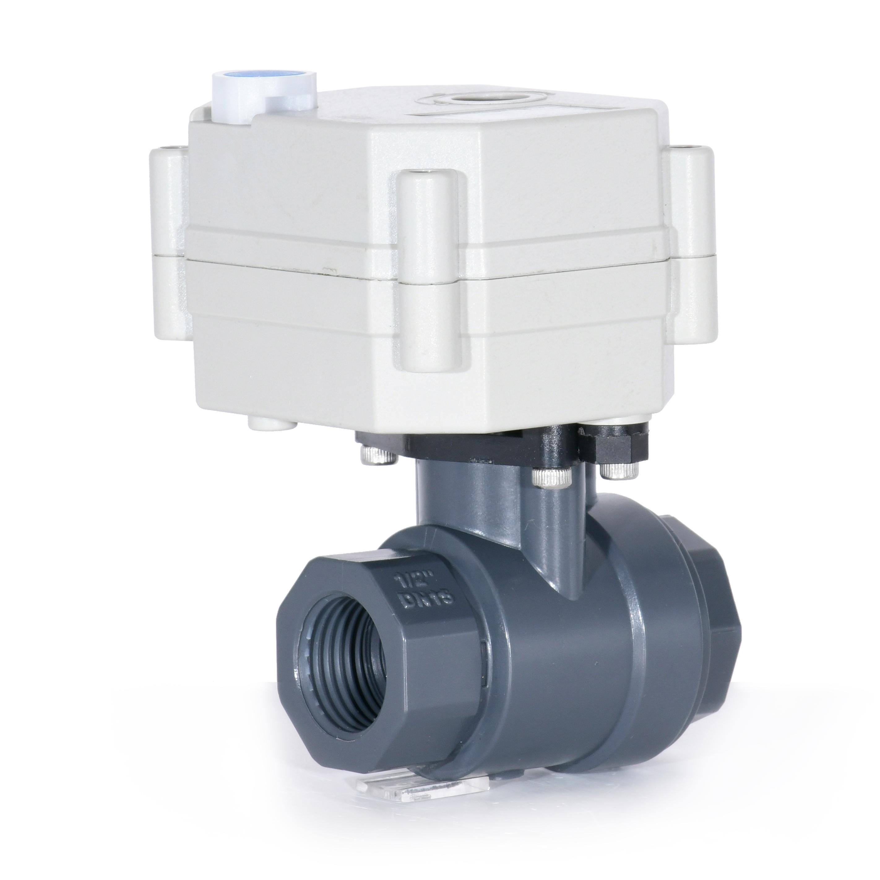
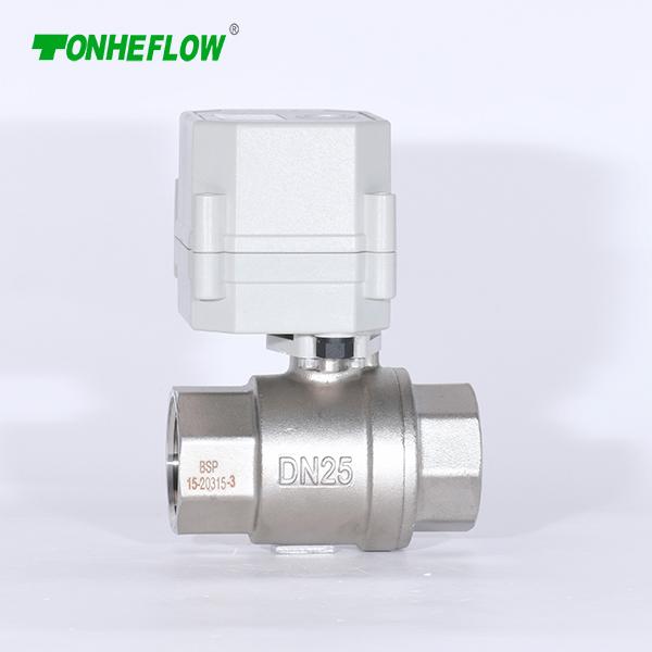
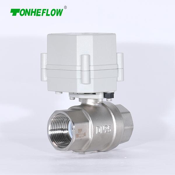
1. Beautiful appearance, compact structure, high precision, large output torque, service life is not less than 70,000 times.
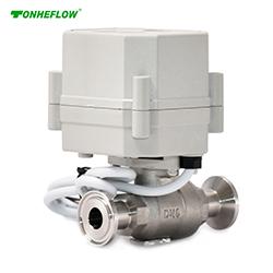
2. The actuator and valve can be assembled from multiple angles, which is convenient for users to allocate space.
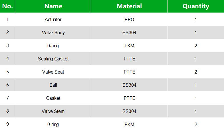
3. Ball valve adopts floating soft seal structure, no drip leakage, suitable for heavy dirt and long-term no action occasions.
4. Protection grade IP67, can be used in relatively humid environment.

1、Red wire connects to DC9-24V positive pole;
2、Black wire connects to DC9-24V negative pole, and it is also 4-20mA/0-5V/0-10V/1-5V/2-10V’s negative pole;
3、Green wire connects to analogy signal positive pole(e.g. 4-20mA/0-5V/0-10V/1-5V/2-10V) ;
4、Yellow wire connects to ERROR output negative pole. Wet contact NPN triode collector output. When there is an error causing the motor to work with excessive current, such as when debris blocks the valve and the ball cannot rotate, the contact is closed; when working normally, the contact open, it only can pull down the external signal. The load is 500mA
5、White wire) connects to position feedback negative pole.
Wet contact NPN triode collector output, OC output PWM signal, 100Hz, 5%-95%, indicating 0-90 degrees. The load is 500mA.
*PWM: Connecting a pull-up resistor to WT and RD, usually use a 1k or 5.1k resistor, recommend to use 1k for power supply below 15V, and 5.1k for over 15V. Oscilloscope clamp connects to power’s negative pole, and oscilloscope probe connects to PWM white wire.
*5%-95% represents duty cycle, which is the ratio of VCC time to the cycle time.
*PMW signal is a signal to give position feedback, the error signal needs to be connected with a 10k resistor to power’s positive pole. When blocking occurs, the error signal to the ground voltage will be lower, at this time, it is able to test signal with oscilloscope.

1. Red cable connects DC9-24V positive pole
2. Black cable connects DC9-24V negative pole
3. Green cable connects position input /control current +/ control voltage 2-10V
4. White cable connects common signal
5. Yellow cable connects position feedback positive,output 2-10V signal

1. Red wire connects to DC9-24V positive pole;
2. Black wire connects to DC9-24V negative pole;
3. Green wire connects to analogy(4-20mA) signal’s positive pole;
4. White wire connects to negative poles of input analogy signal and output signal
5. Yellow wire connects to position feedback positive pole, output signal 4-20mA is the feedback signal.
* When output signal is 4-20mA, the maximum load resistance is the input power voltage (v-2) /0.02, e.g. if the power is 15V, then (15-2)/0.02=650Ω, it is recommended to use a 300Ω load resistor.

1、Red wire connects to DC9-24V positive pole;
2、Black wire connects to DC9-24V negative pole, and it is also 4-20mA/0-5V/0-10V/1-5V/2-10V’s negative pole;
3、Green wire connects to analogy signal positive pole(e.g. 4-20mA/0-5V/0-10V/1-5V/2-10V) ;
4、Yellow wire connects to ERROR output negative pole. Wet contact NPN triode collector output. When there is an error causing the motor to work with excessive current, such as when debris blocks the valve and the ball cannot rotate, the contact is closed; when working normally, the contact open, it only can pull down the external signal. The load is 500mA
5、White wire) connects to position feedback negative pole.
Wet contact NPN triode collector output, OC output PWM signal, 100Hz, 5%-95%, indicating 0-90 degrees. The load is 500mA.
*PWM: Connecting a pull-up resistor to WT and RD, usually use a 1k or 5.1k resistor, recommend to use 1k for power supply below 15V, and 5.1k for over 15V. Oscilloscope clamp connects to power’s negative pole, and oscilloscope probe connects to PWM white wire.
*5%-95% represents duty cycle, which is the ratio of VCC time to the cycle time.
*PMW signal is a signal to give position feedback, the error signal needs to be connected with a 10k resistor to power’s positive pole. When blocking occurs, the error signal to the ground voltage will be lower, at this time, it is able to test signal with oscilloscope.

1. Red cable connects DC9-24V positive pole
2. Black cable connects DC9-24V negative pole
3. Green cable connects position input /control current +/ control voltage 0-10V
4. White cable connects common signal
5. Yellow cable connects position feedback positive,output 4-20mA signal
*When output signal is 4-20mA, the biggest input voltage of load resistance is (v-2)/0.02, e.g. power is 15V, (15-2)/0.02=650Ω, suggest to use 300Ω

1、Red wire connects to DC9-24V positive pole;
2、Black wire connects to DC9-24V negative pole, and it is also 4-20mA/0-5V/0-10V/1-5V/2-10V’s negative pole;
3、Green wire connects to analogy signal positive pole(e.g. 4-20mA/0-5V/0-10V/1-5V/2-10V) ;
4、Yellow wire connects to ERROR output negative pole. Wet contact NPN triode collector output. When there is an error causing the motor to work with excessive current, such as when debris blocks the valve and the ball cannot rotate, the contact is closed; when working normally, the contact open, it only can pull down the external signal. The load is 500mA
5、White wire) connects to position feedback negative pole.
Wet contact NPN triode collector output, OC output PWM signal, 100Hz, 5%-95%, indicating 0-90 degrees. The load is 500mA.
*PWM: Connecting a pull-up resistor to WT and RD, usually use a 1k or 5.1k resistor, recommend to use 1k for power supply below 15V, and 5.1k for over 15V. Oscilloscope clamp connects to power’s negative pole, and oscilloscope probe connects to PWM white wire.
*5%-95% represents duty cycle, which is the ratio of VCC time to the cycle time.
*PMW signal is a signal to give position feedback, the error signal needs to be connected with a 10k resistor to power’s positive pole. When blocking occurs, the error signal to the ground voltage will be lower, at this time, it is able to test signal with oscilloscope.

1. Red cable connects DC9-24V positive pole
2. Black cable connects DC9-24V-negative pole
3. Green cable connects position input /control current +/ control voltage 0-5V
4. White cable connects common signal
5. Yellow cable connects position feedback positive,output 4-20mA signal
*When output signal is 4-20mA, the biggest input voltage of load resistance is (v-2)/0.02, e.x. power is 15V, (15-2)/0.02=650Ω, suggest to use 300Ω
E-mail: tonheflow@china-tonhe.com
Address:Building 3, Xinshun Sme Pioneer Park, Jiangkou Street, Huangyan District, Taizhou city, Zhejiang Province, China


 whatsapp